
Power and wavelength testing
Test the signal transmission strength and wavelength, ensure the signal decoding capability of the receiver, and maintain consistency in wavelength from the transmitter to the receiver.
已有账户?登录以快速结账。


Product Overview:
LC, SC, or pigtail type optical interfaces are available; transceiver module; dual-fiber bidirectional/single-fiber bidirectional options available; 3.3V power supply; metal housing; strong anti-interference capability, compact structure, and easy to use; standard SFF 2×5 pin package; wavelength: 850nm/1310nm/1490nm/1550nm/CWDM/DWDM options available; transmission distance: 0~200km selectable; operating temperature, commercial and industrial grades available; custom SFF 2×5 optical modules of various specifications can be accepted; widely used in aerospace, aviation, military, shipbuilding, power, railway, medical, transportation, communications, telecom operators, industrial control, power control, and other major fields.
Product Description:
Full-duplex LC socket with optical interface compatible;
operating data rate up to 2.5Gbps;
single 3.3V power supply;
LVPECL signal input/output
; LVTTL transmitter disable input;
LVTTL signal detection output;
small 2×10 pin package;
low electromagnetic interference and excellent electrostatic discharge protection;
IEC-60825 compliant;
RoHS 6 compliant;standard
operating temperatureindustrial temperature: -40~85°C
Interconnecting
Gigabit Ethernet
SONET/SDH devices with
Fibre Channel links
and other optical links
Standard
conforms to MSA, SFF
conforms to SFF-8472 standard.
Our strengths
lie in our advanced technology, extensive experience,
independent R&D and meticulous manufacturing, customizable
solutions with imported chips, stable performance,
comprehensive compatibility, and expert personnel to solve technical problems.
Our DDM digital diagnostic real-time monitoring module has undergone
specialized testing and verification, achieving satisfactory performance across all specifications.
Specification
| absoluteHighestRatings | ||||
| parameter | Symbol | Min | Max | unit |
| Storage temperature | TS | -40 | 85 | °C |
| power supply voltage | VCC | 0 | 3.6 | In |
| relative humidity | RH | 5 | 95 | % |
| welding temperature | 260/10 | °C/S | ||
| Recommended operating conditions | ||||||
| parameter | Symbol | Min | typical | Max | unit | Notes |
| Operating box temperature | TC | -5 | 70 | °C | SFF-2×5-2.5G-2Km-MM850 | |
| -40 | 85 | |||||
| power supply voltage | VCC | 3.13 | 3.3 | 3.47 | In | |
| Data rate | 2.5 | Gbps | ||||
| Fiber length 9/125μm, core SMF | 10 | kilometer | ||||
| Electrical characteristics | ||||||
| parameter | Symbol | Min | typical | Max | unit | Notes |
| Total supply current | International Cricket Council | 300 | m.a. | |||
| transmitter | ||||||
| Transmitter differential input voltage | 400 | 2400 | mV | |||
| Tx_Fault Output Voltage - High | fertile | 2.4 | VCC | In | LVTTL | |
| Tx_Fault Output Voltage - Low | roll | 0 | 0.4 | In | LVTTL | |
| Tx_Disable Input voltage - high level | HIV | 2 | VCC | In | LVTTL | |
| Tx_Disable Input Voltage - Low | WILL | 0 | 0.8 | In | LVTTL | |
| Input differential impedance | Tianjin | 85 | 100 | 115 | Oh | |
| receiver | ||||||
| Receiver differential output voltage | 600 | 1600 | mV | |||
| Electrical characteristics | ||||||
| parameter | Symbol | Min | typical | Max | unit | Notes |
| Standard Definition Output Voltage - High | fertile | 2.4 | VCC | In | LVTTL | |
| Standard definition output voltage - low | roll | 0 | 0.4 | In | LVTTL | |
| Output differential impedance | SALTY | 90 | 100 | 110 | Oh | |
| Optical emitter carbonate action | ||||||
| parameter | Symbol | Min | typical | Max | unit | Notes |
| Average output power | pouting | -9 | -3 | dBm | ||
| center wavelength | λc | 1260 | 1310 | 1360 | NM | |
| Spectrum bandwidth (-20dB) | Dl | 1 | NM | |||
| Side mode suppression ratio | SMSR | 30 | decibel | |||
| extinction ratio | emergency room | 8.2 | decibel | |||
| Relative intensity noise | wheel | -128 | dB/Hz | |||
| Optical return loss | 12 | decibel | ||||
| Transmitter and Proliferation Penalty | TDP | 3.2 | decibel | |||
| Transmitter power off | POFF (Executive) | -45 | dBm | |||
| Output eye diagram | Compliant with IEEE 802.3ae standard | |||||
| OpticsReceiver characteristics | ||||||
| parameter | Symbol | Min | typical | Max | unit | Notes |
| center wavelength | λc | 1260 | 1610 | NM | ||
| Receiver sensitivity | PSEN | -18 | dBm | Note 1 | ||
| Input saturation power (overload) | PSAT | 0.5 | dBm | |||
| Receiver reflectivity | -12 | decibel | ||||
| SD declaration level | Adventist Church | -19 | dBm | |||
| SD De-Assert Level | SDD | -35 | dBm | |||
| SD hysteresis | HYS | 0.5 | 6 | decibel | ||
Note 1. Ripple measurement was performed using a PRBS223-1, at 2.488 Gbps, with an ER of 8.2 dB and a BER of 1 × 10⁻¹².
Product Dimensions
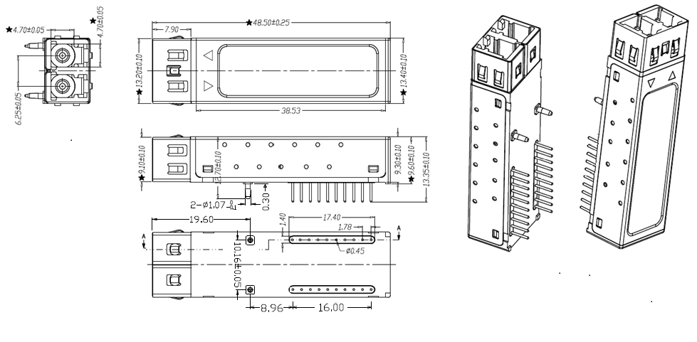
Test the signal transmission strength and wavelength, ensure the signal decoding capability of the receiver, and maintain consistency in wavelength from the transmitter to the receiver.

Test the bit error rate and packet loss rate, to make them meet the corresponding standards and ensure the performance of transceivers.

Test the transceivers' eye diagram situation, receiving sensitivity, extinction ratio, wavelength, light-emitting, light-receiving, current and voltage, to ensure the signal quality, stability and reliability of the transmission.

Check the end face of the transceivers and keep them clean for more stable data transmission, better performance, and durability.

Every module is quality tested for compatibility in the multi-brand switches environment, guaranteeing flawless operations.