
Power and wavelength testing
Test the signal transmission strength and wavelength, ensure the signal decoding capability of the receiver, and maintain consistency in wavelength from the transmitter to the receiver.
已有账户?登录以快速结账。


The CSFP optical module series is a high-stability and high-density module independently developed and produced by AndXe. With a dual BD design, it boasts high reliability and enhanced board density; 1310/1490; 1310/1550; 1270/1330... multiple wavelengths available; international mainstream standard LC connector; compliant with CSFP MSA Option2 and SFF-847; comes with DDM by default; operating temperature, available in commercial and industrial grades; widely used in various fields such as broadcasting and television, telecommunications, mobile, China Unicom, aerospace, aviation, military, ships, electricity, railway, medical, transportation, communication, telecom operators, industrial control, power control, etc
Product Description
Dual BD design, high reliability, and enhanced board density
1310/1490; 1310/1550; 1270/1330... multiple wavelengths available
International mainstream standard LC connector
Transmission distance: 40Km
Speed: 2.5G
Compliant with CSFP MSA Option2 and SFF-847
Operating voltage +3.3V
Optional with/without DDM; default with DDM
Operating temperature, available in commercial and industrial grades
Application
Ethernet, SONET/SDH, Fibre Channel
Single-fiber bidirectional; RoHS compliant
Our Advantages
Excellent skills and rich experience
Independent research and development, craftsmanship and intelligence, customizable needs
Imported chips, high-quality solutions, stable performance
Fully compatible. Senior talents to solve technical issues
DDM digital diagnosis real-time monitoring module status
Special test: All performance items have been tested and meet the required standards
ABSOLUTE MAXIMUM RATING
| Parameter | Symbol | Min. | Max. | Unit | Notes |
| Storage Ambient | TSTG | -40 | 85 | °C | |
| Operating Case | Tc | -40 | 85 | °C | |
| Operating Humidity | OH | 5 | 95 | % | |
| Power Supply Voltage | VCC | 0 | 4 | V | |
| Power Consumption | 1.5 | W |
RECOMMENDED OPERATING CONDITION
| Parameter | Symbol | Min. | Typ. | Max. | Unit | Notes |
| Operating Case | Tc | 0 | 70 | °C | Commercial | |
| Temperature | Tc | -40 | 85 | °C | Industrial | |
| Power Supply Voltage | VCC | 3.13 | 3.3 | 3.47 | V | |
| Power Supply Current | ICC | 400 | 450 | mA | ||
| Date Rate | 2.5 | Gbps | ||||
| Data Rate Drift | -100 | +100 | PPM |
TRANSMITTER OPTICAL CHARACTERISTICS
| Parameter | Symbol | Min. | Typ. | Max. | Unit | Notes |
| Centre Wavelength | λC | 1480 | 1490 | 1500 | nm | |
| Spectral Width (RMS) | σ | 3 | nm | |||
| Average Output Power | Po | -5 | 0 | dBm | ||
| Turn off Average Output Power | -45 | dBm | ||||
| Extinction Ratio | ER | 8.2 | dB | |||
| Optical Return Loss Tolerance | 12 | dB | ||||
| Output Optical Eye IEEE Std 802.3ah | PRBS 27-1 @2.5Gbps | |||||
| Side Mode Suppression Ratio | SMSR | 30 | ||||
TRANSMITTER ELECTRICAL CHARACTERISTICS
| Parameter | Symbol | Min. | Typ. | Max. | Unit | Notes |
| Data Input Differential Swing | 200 | 2400 | mV | |||
| Input Differential Impedance | 85 | 100 | 115 | Ω | ||
| TX Disable | Disable | 2 | VCC+0.3 | V | ||
| Enable | -0.3 | 0.8 | V | |||
| TX Fault | Normal | -0.3 | 0.4 | V | ||
| Fault | 2.4 | VCCHOST | V |
RECEIVER OPTICAL CHARACTERISTICS
| Parameter | Symbol | Min. | Typ. | Max. | Unit | Notes |
| Operating Wavelength | λC | 1260 | 1310 | 1360 | nm | |
| Sensitivity | SEN | -20 | dBm | PRBS 27 -1BER≤10E-12 , ER=8.2dB | ||
| Saturation Optical Power | SAT | -3 | dBm | |||
| Loss of Signal De-Assert Level | LOSD | -21 | dBm | |||
| Loss of Signal Assert Level | LOSA | -36 | dBm | |||
| Loss of Signal Hysteresis | 0.5 | 5 | dB |
RECEIVER ELECTRIAL CHARACTERISTICS
| Parameter | Symbol | Min. | Typ. | Max. | Unit | Notes |
| Data Output Differential Swing | 200 | 2400 | mV | |||
| Loss of Signal – Low | -0.3 | 0.4 | V | |||
| Loss of Signal – High | 2.4 | VCCHOST | V |
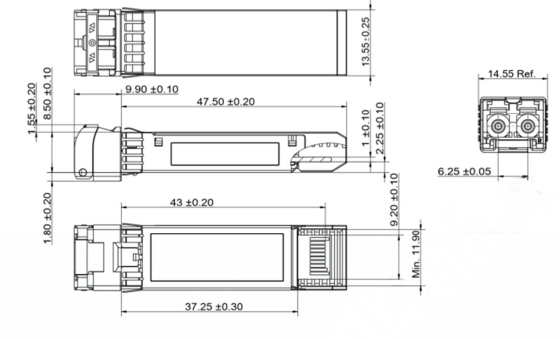
PACKAGE OUTLINE
Test the signal transmission strength and wavelength, ensure the signal decoding capability of the receiver, and maintain consistency in wavelength from the transmitter to the receiver.

Test the bit error rate and packet loss rate, to make them meet the corresponding standards and ensure the performance of transceivers.

Test the transceivers' eye diagram situation, receiving sensitivity, extinction ratio, wavelength, light-emitting, light-receiving, current and voltage, to ensure the signal quality, stability and reliability of the transmission.

Check the end face of the transceivers and keep them clean for more stable data transmission, better performance, and durability.

Every module is quality tested for compatibility in the multi-brand switches environment, guaranteeing flawless operations.